Robotics Design Project
|
The code below is the same code in the blog, "Testing Blog". The picture that follows shows our final design that we came up with, and some strengths about the project includes that it is pretty much water proof. The housing allows the wires and spool inside to stay dry for the most part. The yellow 3-D printed part also covered the circuit board of the temperature sensor to keep it still and also protects it from water. Some improvements include drilling the hole where the axle goes through larger. When the axle rotates, there was this squeaking sound and the entire housing bends one way probably because there was friction in the hole of the axle. 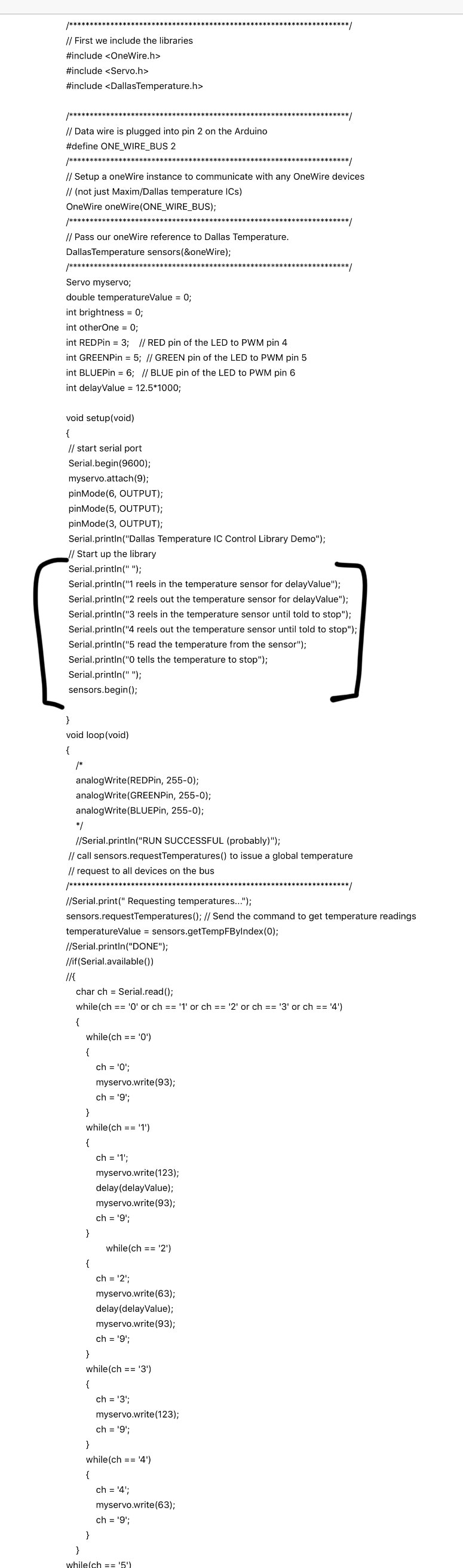 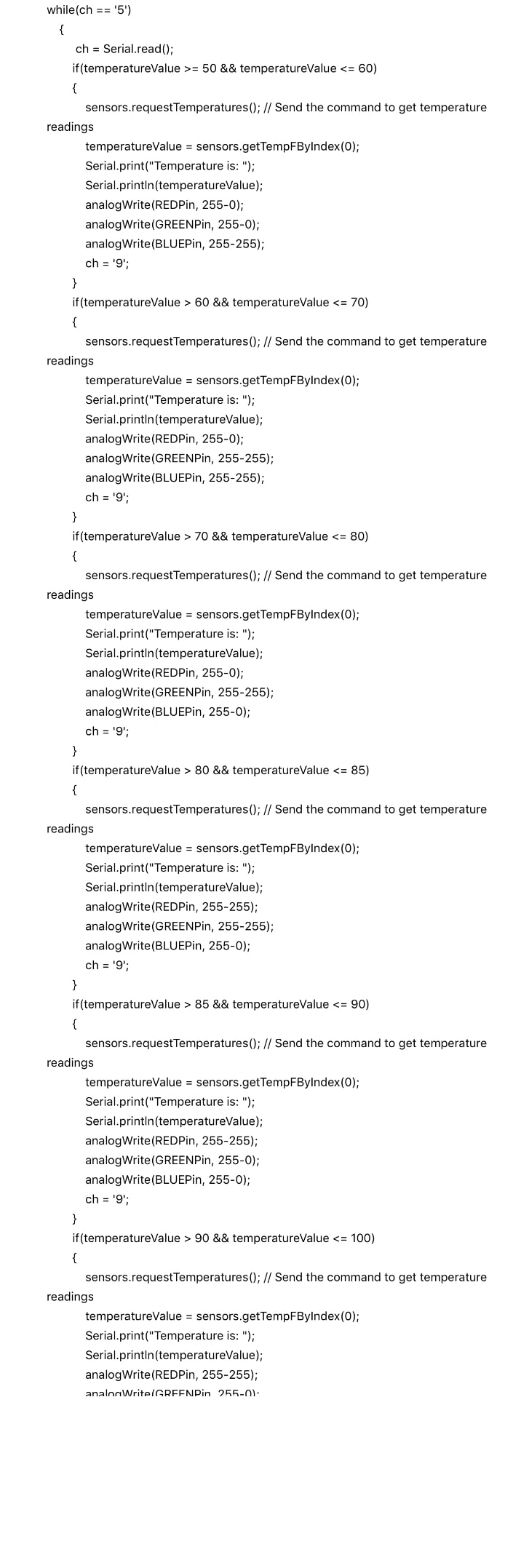 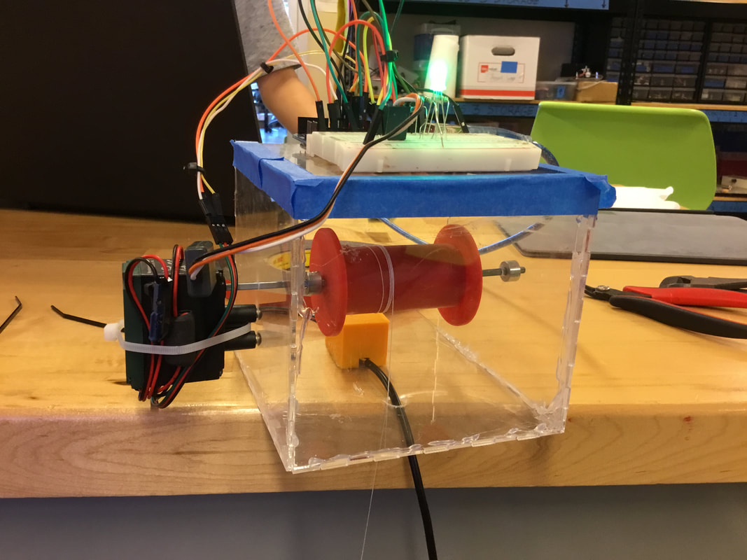 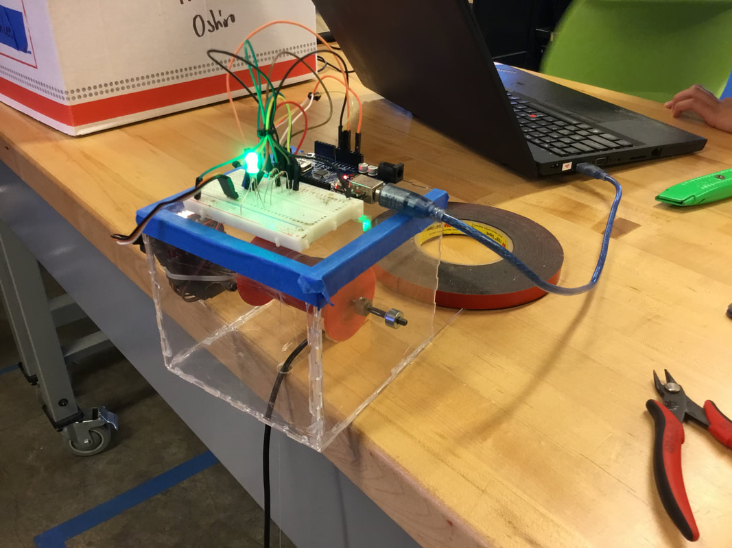
0 Comments
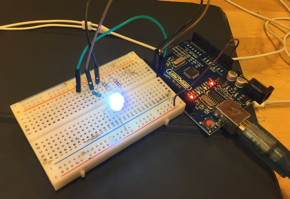
We tested the temperature sensor in the pool to demonstrate the change in depth and motor portion of our project. Braden is typing on the computer numbers that correspond to commands to be sent to the motor. The portion of the code that is outlined shows the instructions in how to use the code. In the video, Braden presses 1 and 2 to reel in and reel out the spool and temperature sensor. 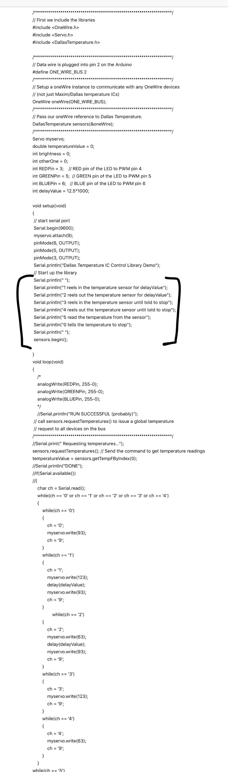 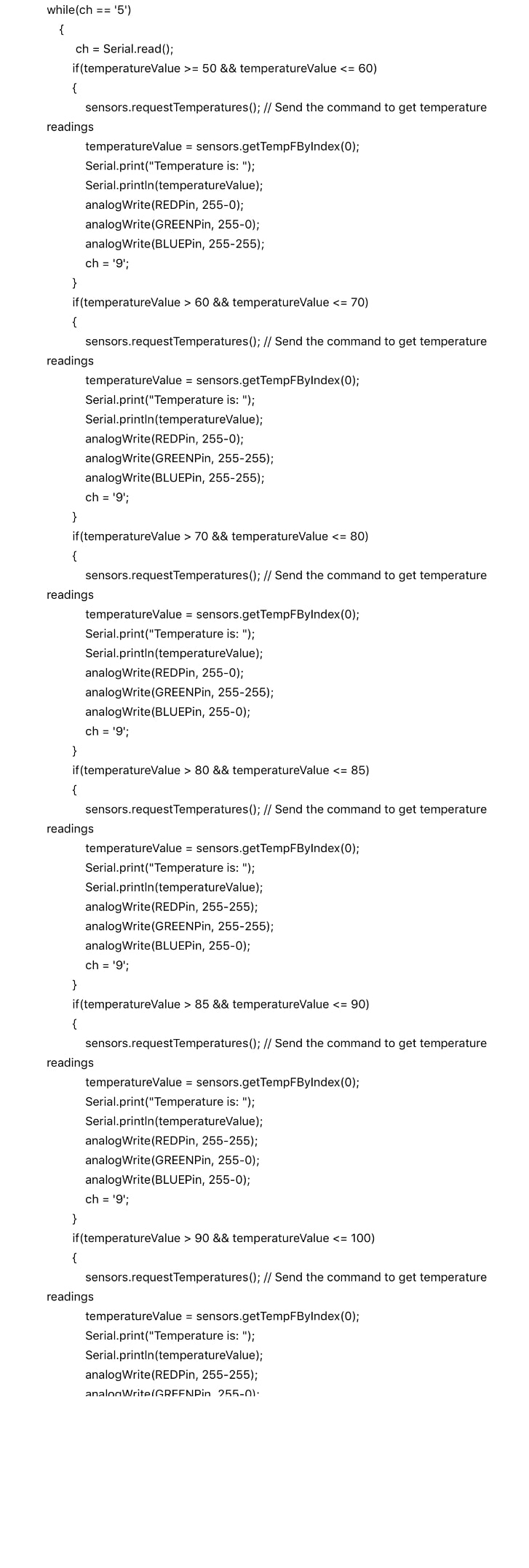 Today we cleaned up the two parts of the spool and glued them together using super glue. Fortunately, both parts fit perfectly. From here, our goal is to work on the housing that we plan to make out of acrylic. Meanwhile, my partner was able to get the RGB LED to light up. His blog is at: https://roboticsbraden.weebly.com/
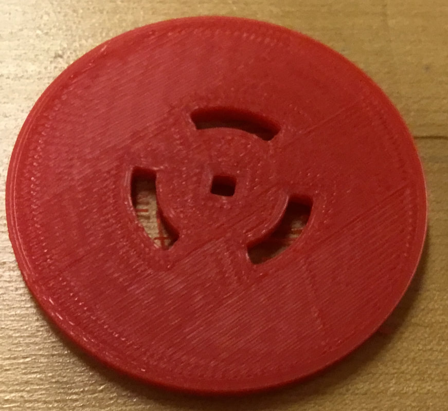
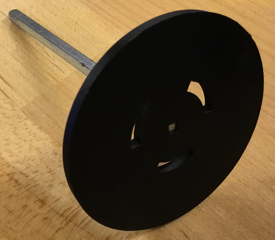
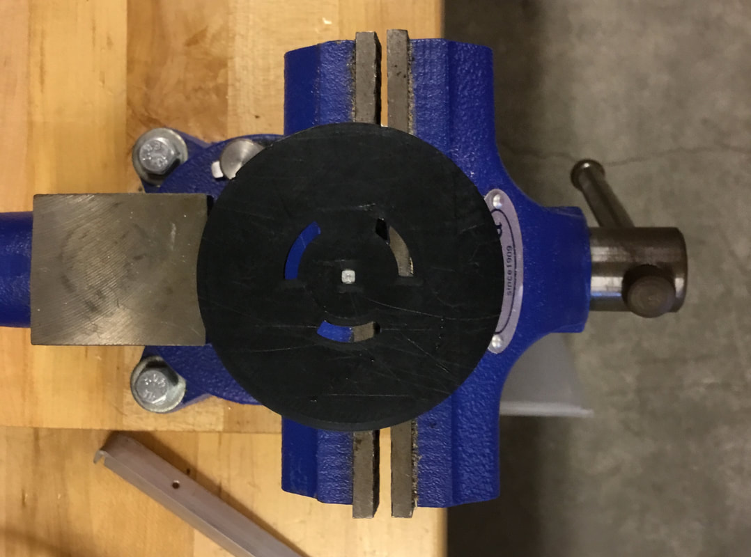
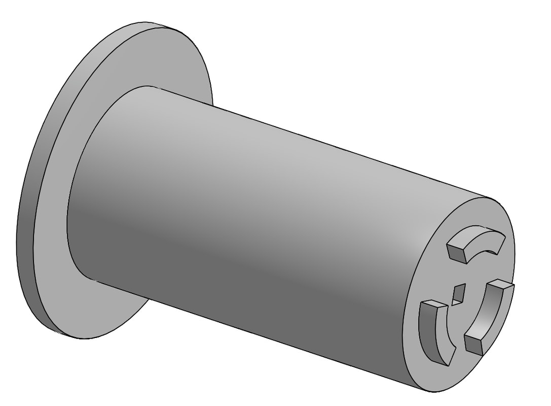
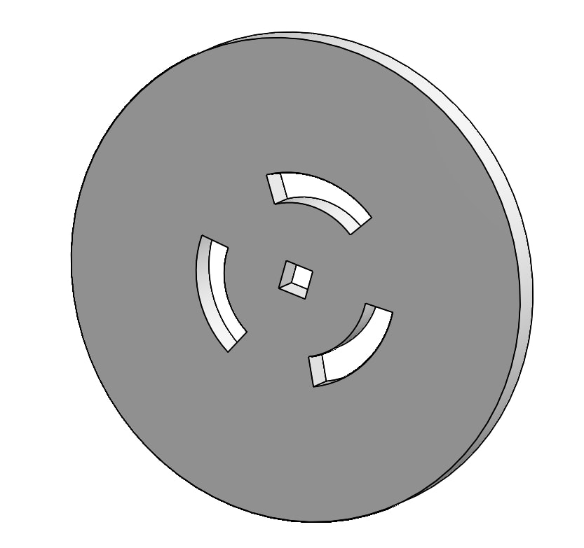
Fortunately, one of our parts came out exactly how we wanted as it fits the axle. However, the part that we increased by 3% did not come out. One, the axle still does not fit into the hole, and two, the 3 notches holes do not fit onto the notch holes. It never came to our realization that when we increased the part by 3%, the middle space between the axle hole and the notch holes will also increase, meaning that the notches won't fit regardless of being larger than the notch being smaller than the hole. To fix this, we manually fixed it on Onshape. First, we increased the axle hole to match the axle hole of the first successful part. then we used "thicken" to remove 0.5 mm around the notch holes on part 2, creating extra room for part 1 to fit into it.
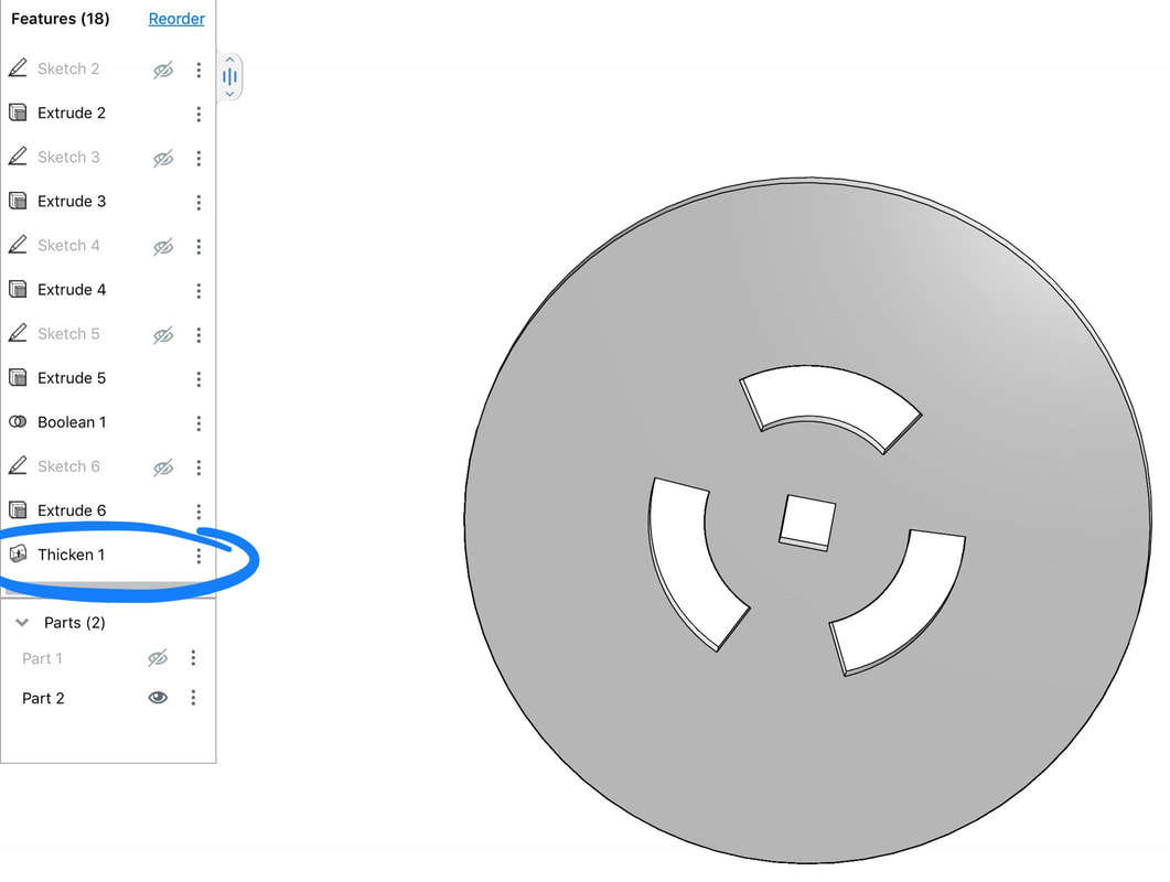 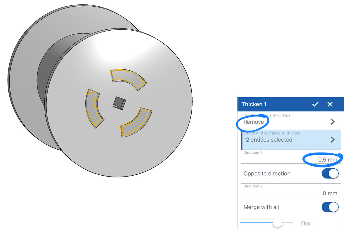 Today, my team attempted to fix the spool. We labeled the larger portion of the spool part 1, and the smaller portion as part 2. On part 1, we made the axle hole larger than part 2. We did this because on the program Simplify3D, we planned to scale part 2 up by 3% because we want the peg holes to be larger, allowing part 1 to fit into part 2 easily and nicely rather than struggling to ram the two parts together. Therefore, the axle hole in part 2 would be larger if we originally designed the two parts to have the same size hole. So we made the hole in part 1 larger to accommodate for enlarging part 2. Meanwhile, my partner has been working on the coding and finalizing the code for the temperature sensor. His blog is at : https://roboticsbraden.weebly.com/
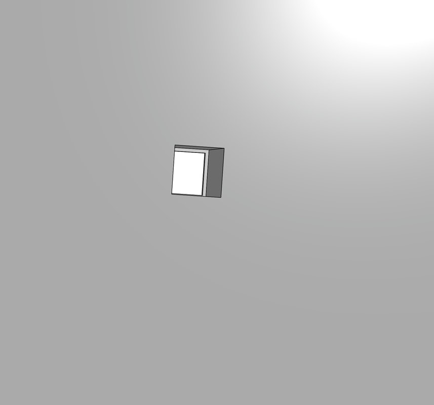
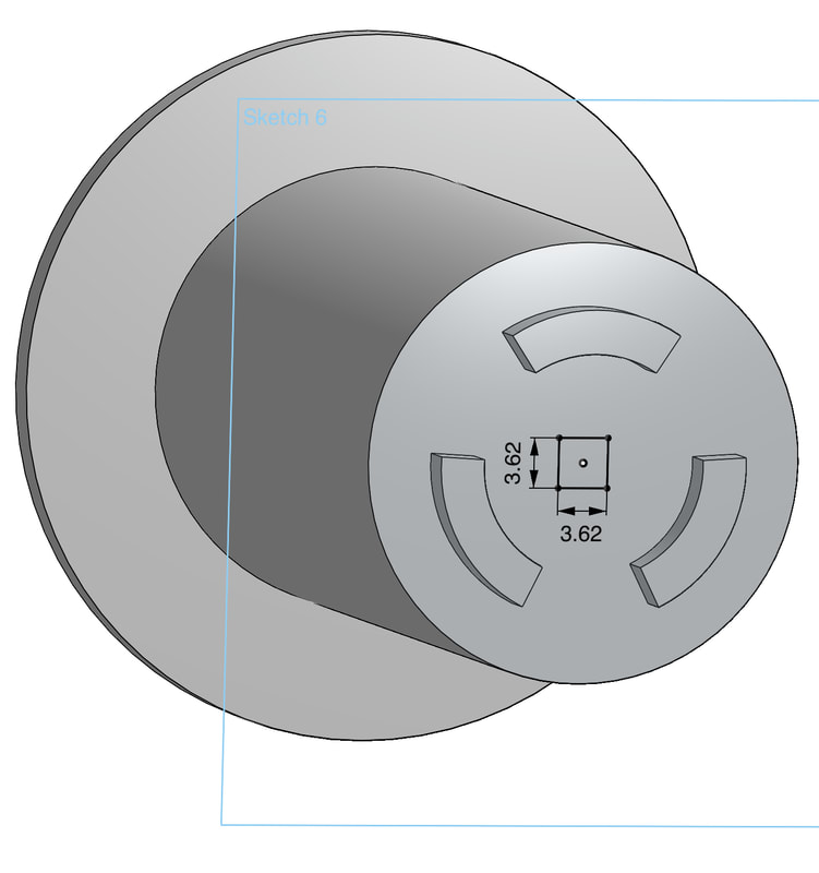
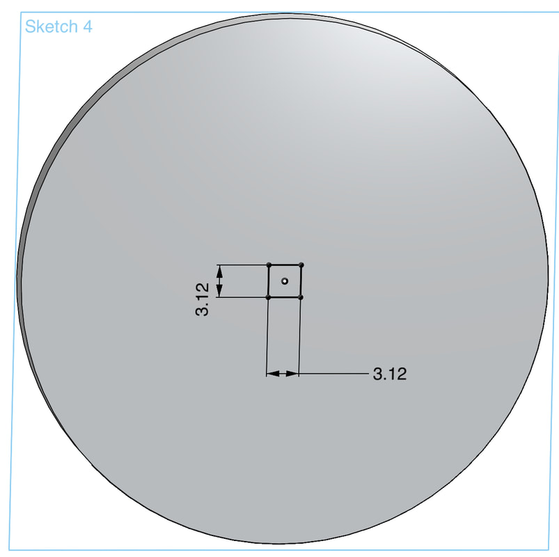
Unfortunately, our 3D printed part did not come out as planned. We should have given more room for the axle as it is a very tight fit and does not pass through the plastic. To fix this, we'll just go back to CAD and adjust the measurements for the center square.
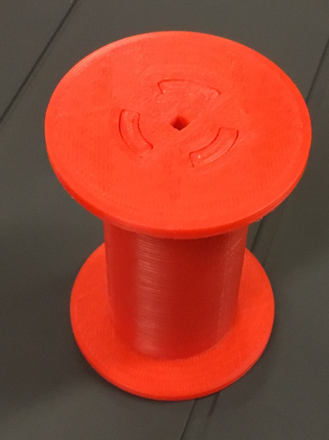
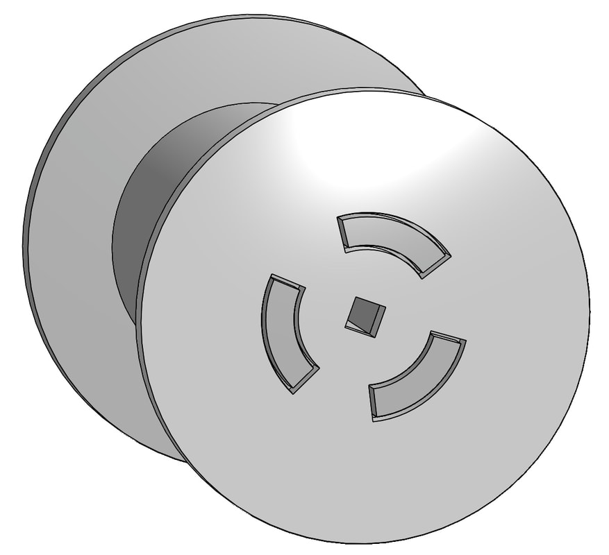
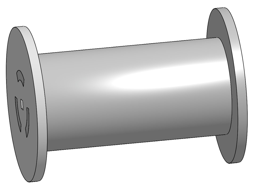
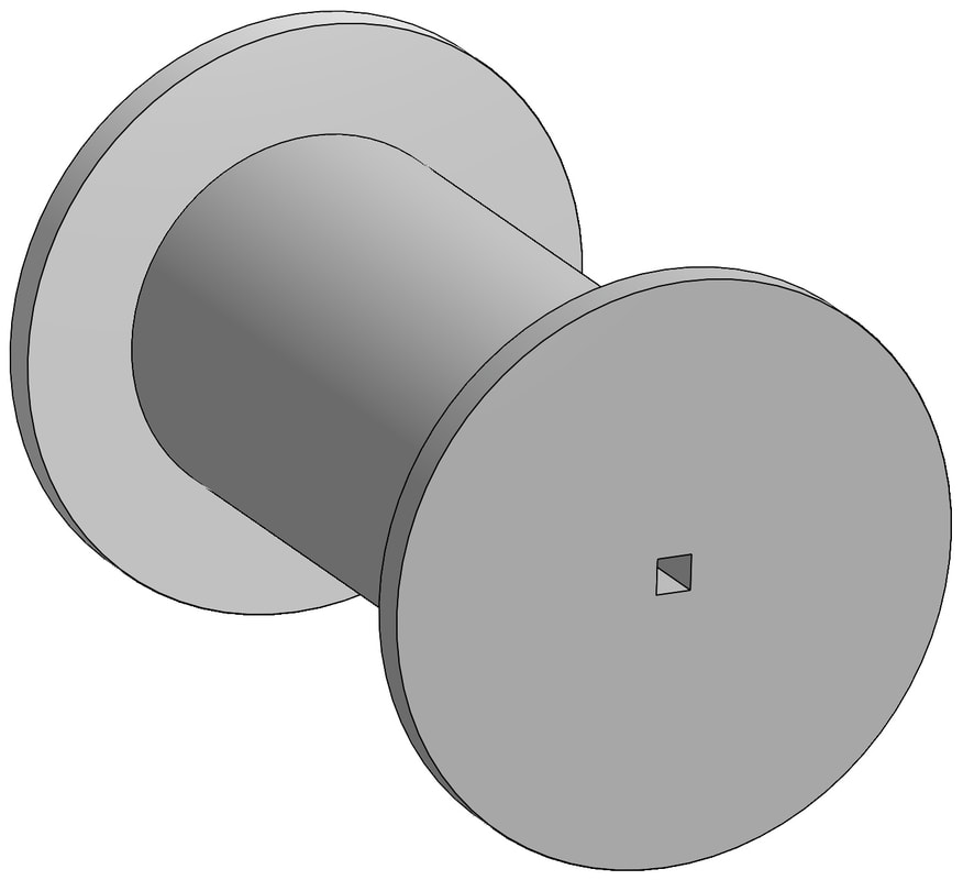
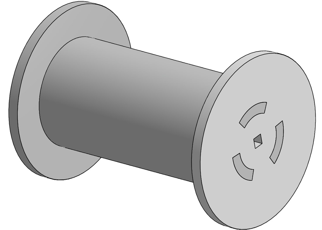
Today, we successfully 3D modeled the spool. We added a small change to the original design. Here, as you can see in the pictures. we added 3 little "pegs" or notches to increase surface area for gluing, making it structurally more strong. Now, our goal will be to 3D model the housing.
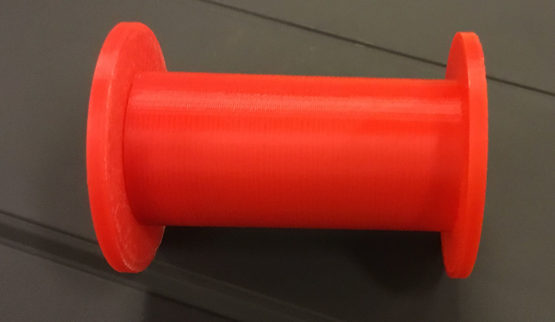
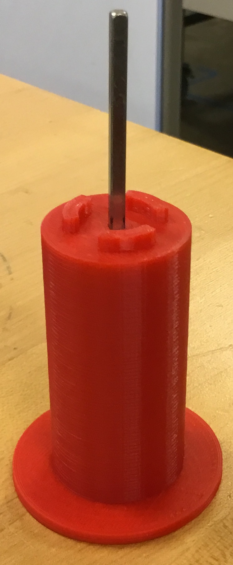
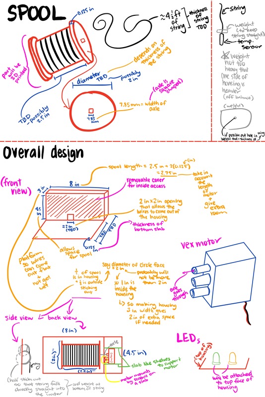
 Our team started to work on the spool, but it came to us that it would be difficult to attach a wire to the temperature sensor since there were 3 other wires that were connecting to the sensor (as shown in the picture circled in blue). So we decided to just wrap the cord that is 3 feet long (our goal was 5 feet long but 3 feet should be okay) around a spool. The sample spool shown in the picture is similar to what we plan to use, although we still have to 3D print a new one with the correct size for the axle. The terminal will be mounted onto the housing to prevent it from falling into the water. This shouldn't affect the rest of the dimensions as the sample spool has similar measurements of what we were going to plan to use. While doing this, my partner started on working on and planning the sample code (his blog is at: https://roboticsbraden.weebly.com) 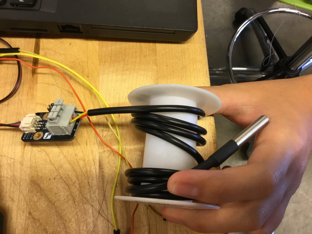 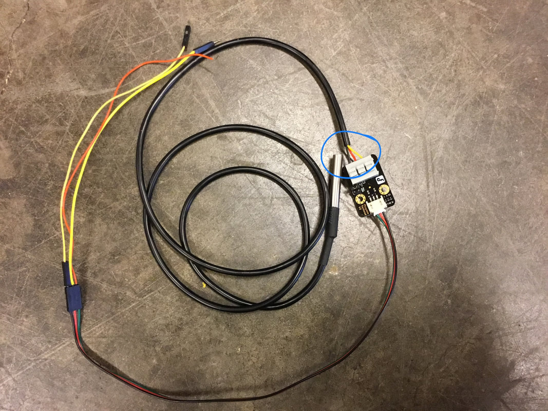 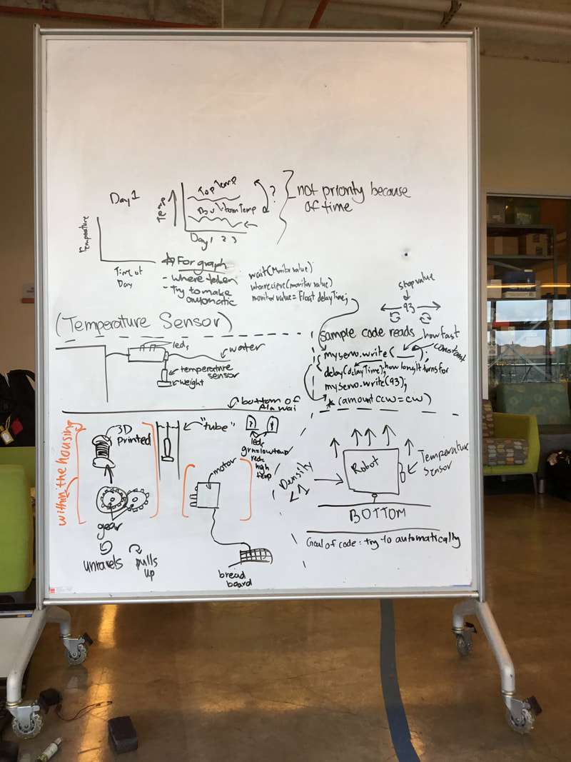 The main mechanism to change the elevation of the temperature sensor is using a gear and a spool with string. When the gear rotates one direction, it will turn the entire spool allowing string to unravel, lowering the elevation of the sensor. There will be a weight at the bottom of the string to allow the string to remain straight in the water. The gears are vex gears and will rotate using a motor, connected to a breadboard that will be outside housing, on the dock, along with the power supply (the computer). If we have time, our team will try to automatically create graphs with the data collected. We also may include a tubing that surrounds the string underwater to prevent large objects from hitting it or tearing the string. There will possibly be a string that attaches to the dock and keeps the housing stationary. On top, where it is visible, will be LEDs that will blink green and red. Green for cooler temperatures in a given range (TBD) and red for warmer temperatures in a given range (TBD). The 3D printed part will be the spool.
We met the design requirements of using the temperatures sensor, the housing will be waterproof, the thermometer will be able to be underwater and change depths, able to stay stationary through the string tied to the dock and the housing, visual representation with the LEDs, has a 3D printed part (spool), power source (computer). |